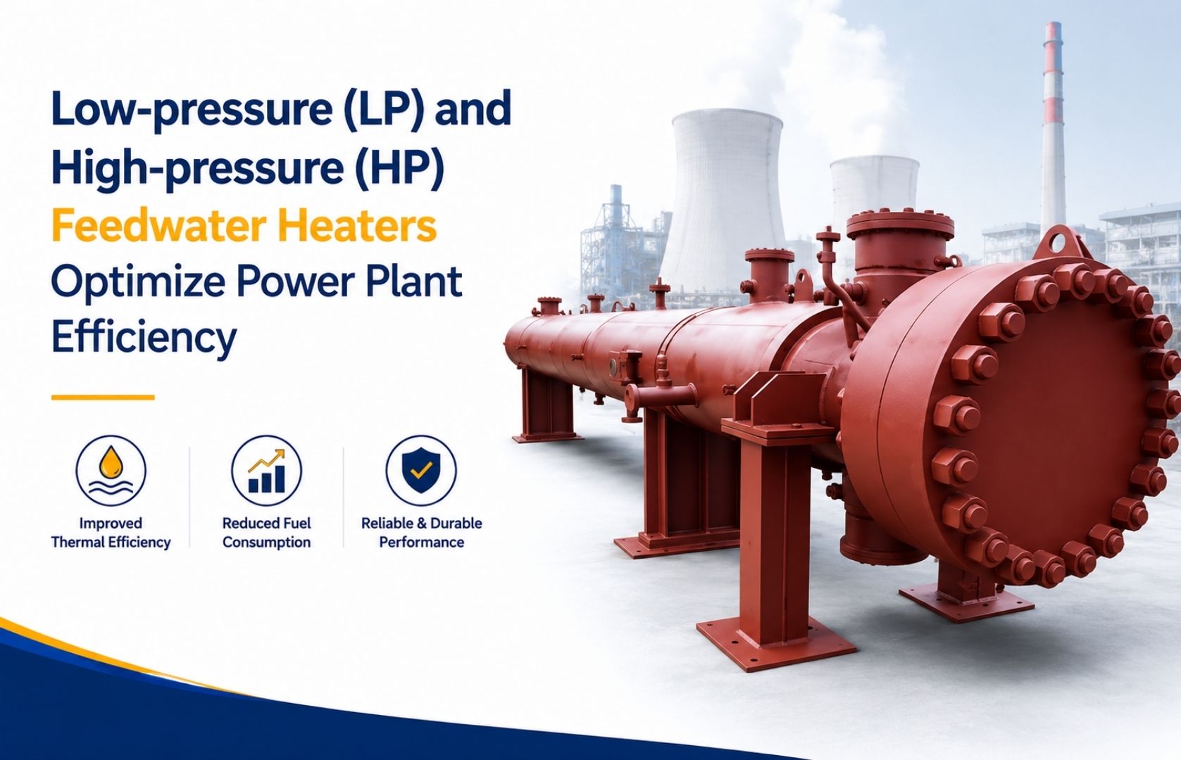
In the current context, power generation necessitates maximum energy production with less fuel utilization. In thermal power stations, attaining ultimate thermodynamic performance not only requires capturing but also reusing heat that would otherwise be wasted. Key to this heat recovery strategy is the Feed Water Heater, which is a necessary heat exchange tool designed to preheat boiler feedwater before it enters the steam generator.
Through the utilization of the low-pressure (LP) and high-pressure (HP) feedwater heating processes, the amount of heat loss is minimized, fuel consumption is reduced, and boiler lifespan is prolonged. As an industry-leading feed water heater manufacturer, Jet Flow Technologies engineers advanced thermal systems designed to keep power plants operating at peak thermal proficiency.
What is a Feed Water Heater?
A Feed Water Heater is a specific kind of shell-and-tube heat exchanger, which is applied in the Rankine steam cycle to increase the temperature of water being supplied to the boiler. Rather than using raw fuel to heat cold condensate water from ambient levels to operational temperatures, the system uses steam bled from intermediate points of the steam turbine.
Why Feed Water Heating Matters in a Steam Cycle
In a standard Steam Cycle, cold condensate allows the condenser to return to the boiler at a pretty low temperature. If unheated water enters the steam drum directly, it causes severe thermal stress across metal walls, enhances fuel consumption, and decreases overall thermodynamic effectiveness.
Preheating feedwater delivers three main thermodynamic benefits:
- Reduces Fuel Demand: Less primary fuel (coal, gas, or biomass) is required to raise water to its boiling point.
- Minimizes Thermal Shock: Prevents extreme temperature gradients across boiler tubes and drum walls.
- Optimizes Latent Heat Usage: Recovers latent heat from extracted steam before it reaches the main condenser.
Working Principle of a Feed Water Heater
The core operation of a power plant feed water heater relies on two major thermodynamic concepts: Steam Extraction and Regenerative Heating.
Step 1: Steam Extraction from the Turbine
During the expansion process of high-pressure steam in the steam turbine for the generation of mechanical energy, a certain amount of steam is bled out at different pressure points. This steam is not allowed to move directly to the condenser but is rather led to the feedwater heater.
Step 2: Heat Transfer Inside the Shell and Tube Heat Exchanger
The extraction steam enters the shell side of the shell and tube heat exchanger, while boiler feedwater flows through the tubes. As the steam meets the outer surfaces of the tubes, it condenses and releases its latent heat. This heat passes through the tube walls and raises the temperature of the feedwater flowing inside.
As the steam and water never mix, the system offers effective heat transfer while preserving water quality and preventing contamination.
Step 3: Condensate Collection
Once the extraction steam has transmitted its thermal energy, it condenses into water. This condensate is gathered and routed back into the condensate system or flowed to lower-pressure feedwater heaters, enabling additional heat recovery and enhancing the overall regenerative heating procedure.
Step 4: Preheated Feedwater Enters the Boiler
This hot feedwater leaves the heater at a considerably high temperature and proceeds within the feedwater circuit to the economizer and boiler. As the water is preheated, less fuel is needed by the boiler to turn this water into high-pressure steam.
This continuous cycle of steam extraction, regenerative heating, and heat recovery helps to enhance the efficiency of the entire steam cycle while reducing fuel consumption and increasing the overall performance of the power plant.
Difference Between Low Pressure Feed Water Heater and High Pressure Feed Water Heater
Feedwater systems are divided into low-pressure and high-pressure stages based on their location relative to the boiler feed pump (BFP).
Feedwater systems are divided into low-pressure and high-pressure stages based on their location relative to the boiler feed pump (BFP).
| Parameter | Low Pressure (LP) Feed Water Heater | High Pressure (HP) Feed Water Heater |
|---|---|---|
| Location in Cycle | Between condensate extraction pump (CEP) and deaerator | Between boiler feed pump (BFP) and boiler inlet |
| Operating Pressure | Lower shell and tube operating pressure (< 30-40 bar) | High pressure on tube side (up to 200+ bar) |
| Source of Steam | Low-pressure turbine bleed points | High-pressure or intermediate-pressure turbine bleed points |
| Tube Side Fluid | Condensate water from the main condenser | Compressed feedwater from the boiler feed pump |
| Construction Robustness | Standard shell thickness with U-tube bundles | Thick-walled forged headers, heavy shell plates, and alloy tubes |
| Primary Risk Managed | Vacuum/low-pressure vapor condensation | High mechanical stress, thermal fatigue, and tube joint erosion |
Where Are LP and HP Feed Water Heaters Installed?
A typical power generation layout follows a sequential arrangement:
- LP Feed Water Heater Stage: Located downstream of the condenser and Condensate Extraction Pump (CEP). Condensate flows through one or more LP heaters before entering the open deaerator heater.
- Deaerator: Removes dissolved gases (oxygen and carbon dioxide) while providing intermediate preheating.
- Boiler Feed Pump (BFP): Elevates water pressure significantly to match boiler drum pressure.
- HP Feed Water Heater Stage: Positioned between the BFP discharge and the boiler economizer. Water passes through multiple HP heaters, absorbing high-temperature heat from high-pressure turbine extraction steam before entering the boiler.
Shell and Tube Heat Exchanger Design
Most industrial feedwater preheaters use a shell and tube heat exchanger configuration, engineered with three primary thermal zones:
- Desuperheating Zone: High-temperature extraction steam enters this zone first, transferring sensible heat to high-temperature feedwater leaving the heater.
- Condensing Zone: The main section where extraction steam undergoes phase change from vapor to liquid, releasing latent heat at constant saturation temperature.
- Subcooling (Drain Cooling) Zone: Condensed steam (drain liquid) is subcooled by incoming cold feedwater before passing to the next lower-pressure heater stage or condenser.
Advantages of Feedwater Heaters
Installing custom-engineered feedwater heaters from a reliable feedwater heater supplier yields substantial operational advantages:
Higher Thermal Efficiency: By capturing thermal energy from extracted steam, the Rankine cycle approaches Carnot efficiency, yielding more megawatt-hours per unit of heat input.
Better Boiler Efficiency: Entering feedwater is close to saturation temperature, requiring less firing duty in the furnace and reducing thermal strain on boiler tubes.
Improved Turbine Efficiency: Extracting steam reduces exhaust volume flow at the final turbine stages, mitigating exhaust losses and blade erosion caused by moisture droplets.
Heat Recovery: Steam condensate drains are cascaded sequentially, maximizing total Heat Recovery across the power island.
Lower Fuel Consumption: Lower heat consumption translates directly into reduced daily fuel expenditure.
Reduced Emissions: Decreased fuel consumption leads to lower greenhouse gas emissions (CO2, NOx, and particulate matter) per megawatt generated.
Better Plant Reliability: Preheating minimizes thermal expansion cycles across heavy boiler drums and piping header welds.
Design Standards Followed by Jet Flow Technologies
At Jet Flow Technologies, every ASME Feed Water Heater and TEMA Heat Exchange assembly is engineered in accordance with global technical benchmarks:
- HEI Standards (Heat Exchange Institute): Standards for closed feedwater heaters governing thermal margins, venting design, drain cooling zones, and mechanical clearances.
- ASME Codes (Section VIII & Section I): Guarantees structural pressure containment, materials selection, non-destructive examination (NDE), and pressure vessel certification.
- TEMA Standards (Tubular Exchanger Manufacturers Association): Regulates mechanical tolerances, tube sheet designs, baffle spacing, and construction classes.
Every unit built by Jet Flow Technologies is analyzed using innovative thermal, hydraulic, and mechanical engineering software (including 3D thermal-fluid modeling and finite element stress analysis) to guarantee reliable performance under severe thermal cycling and high pressure conditions.
How to Choose the Right Feed Water Heater Manufacturer
When choosing a feed water heater manufacturer, evaluate the following technical criteria:
- Thermal Engineering Capability: Proven expertise in sizing desuperheating, condensing, and subcooling zones.
- Metallurgical Mastery: Proficiency to work with high-grade carbon steels, low-alloy steels, and stainless steel tubing tailored for water chemistry.
- Quality Assurance & Testing: Robust internal NDT capabilities (radiography, ultrasonic testing, helium leak detection, and hydrostatic testing).
- Lifecycle Support: Emergency retubing, channel header maintenance, and field servicing.
Why Choose Jet Flow Technologies?
Jet Flow Technologies is a primary feedwater heater supplier delivering custom-engineered thermal management solutions for industrial co-generation plants, utility power stations, and process facilities worldwide.
- Tailored Thermal Designs: Custom zone sizing optimized for your plant’s exact turbine bleed steam parameters.
- Full Code Compliance: Fully certified under ASME, HEI, and TEMA standards.
- Advanced Fabrication: State-of-the-art orbital welding, automated tube-to-tubesheet joint rolling, and high-precision CNC machining.
- Turnkey Support: From initial heat balance calculations to installation commissioning and aftermarket maintenance.
Jet Flow Technologies’ Global Reach
Jet Flow Technologies delivers high-performance machines and other engineered process equipment to consumers across more than 40 countries, supported by production facilities in India, Europe, and Indonesia and a global sales and service network.
- Asia: India, China, Japan, South Korea, Taiwan, Singapore, Malaysia, Indonesia, Philippines
- Europe: United Kingdom, Germany, France, Belgium, Spain, Italy, Greece, Poland
- North America: USA, Canada, Mexico
- South America: Brazil, Argentina, Chile
- Middle East & Africa: Saudi Arabia, UAE, Iran, Iraq, Egypt, Turkey, South Africa, Nigeria, Cameroon, Kenya
- Oceania: Australia
Optimize Your Power Plant Performance with Jet Flow Technologies
Upgrading or replacing your high-pressure feedwater heater or low-pressure feedwater heater is one of the most efficient ways to lower your plant heat rate and increase overall efficiency.
Contact Jet Flow Technologies today to consult with our thermal engineering specialists, request custom heat exchanger designs, or secure high-reliability feedwater heaters built to ASME and HEI standards.
Frequently Asked Questions (FAQs)
What happens if a feedwater heater fails?
Tube leaks or structural failures can cause feedwater to flash into the shell side, tripping turbine protection systems or flooding extraction steam lines. Regular inspections and proper level control prevent heater trips.
What is the main difference between an open and closed feedwater heater?
In an open feedwater heater (like a deaerator), extraction steam and cold water mix directly. In a closed shell-and-tube feedwater heater, water flows inside tubes while steam condenses on the shell side without direct mixing.
Why are high-pressure feedwater heaters placed after the boiler feed pump?
Placing HP heaters downstream of the boiler feed pump ensures that water enters the boiler economizer at high pressure and elevated temperature, optimizing boiler drum heat transfer and preventing thermal shock.